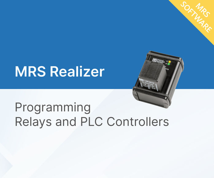
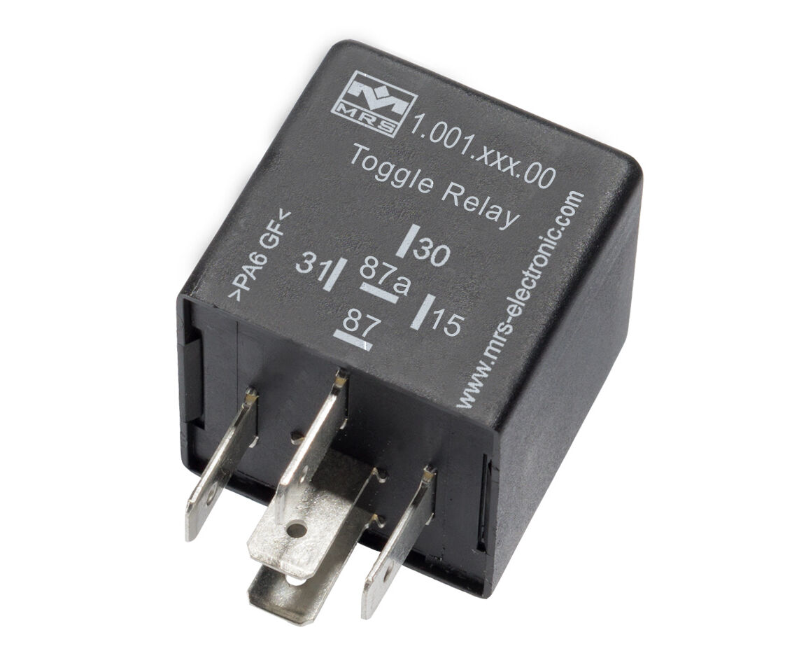
Toggle Relay M1 compact 24 V
go to order options (100128x00)
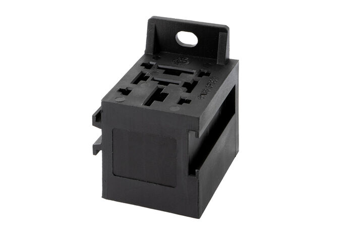
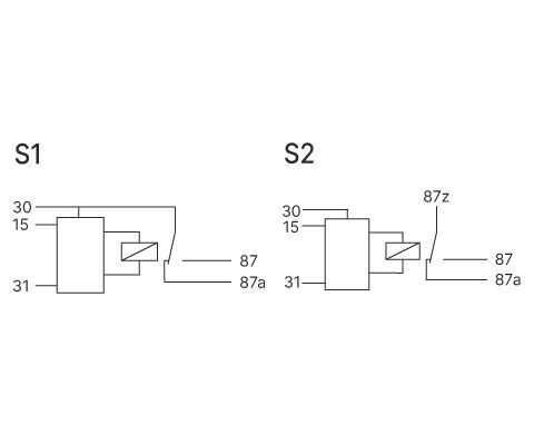
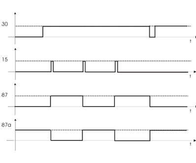
The Toggle Relay is used to switch loads on and off via pushbutton operation. Circuit diagram S1: With the step switching relay a consumer can be switched via a button. If a positive/negative impulse is applied to Terminal 15, the relay switches and holds itself. Another impulse is switched on again (Power surge switch or toggle flip-flop). The terminal 15 is debounced. Circuit diagram S2: The contacts are separate from the control and can therefore be used in links. In this variant, the relay contact is completely potential-free and thus capable of switching alternating voltage. Housing forms can be found in the section housing and basic body.
Note: If you require an order variant with a time limit, please contact us!
Downloads


Technical details
Inputs and Outputs
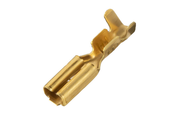
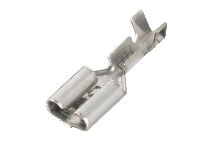
| Number of pins | 5 |
|---|---|
| In-/Outputs (total) | 2 |
| Inputs (total) | 1 |
| Inputs (digital) | 1 |
| Outputs (total) | 1 |
| Relay outputs | 1 |
| Switching current | 15 A NC / 15 A NO |
Mechanical Properties
| IP rating | IP53 |
|---|---|
| Housing material | PA66GF30 |
| Dimensions | 30 × 30 × 30 mm |
| Switching cycles | 100000 |
Programming
| Programming software | MRS Realizer |
|---|
General Information
| Temperature range | -40 to +85°C |
|---|---|
| Operating voltage | 16-32 V |
| Current consumption | 2 mA |
Markings
Order options
| Order no. | Name |
|---|---|
| 1.001.281.00 (100128100) |
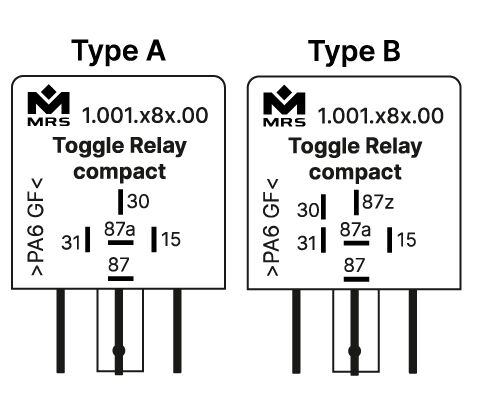
30A, positive edge triggered, Type A, Connection S1
|
| 1.001.282.00 (100128200) |
30A, negative edge triggered, Type A, Connection S1
|
| 1.001.283.00 (100128300) |
30A, positive edge triggered, Type B, Connection S2
|
| 1.001.284.00 (100128400) |
30A, negative edge triggered, Type B, Connection S2
|